| January 29, 2008 | HOME | ||||||||
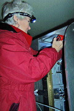
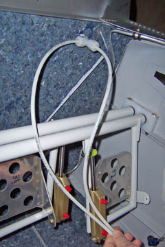
It was still pretty cold in garage today as I reinstalled the rudder peddles to begin work on the final brake plumbing.
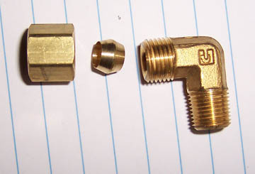
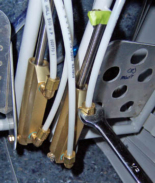
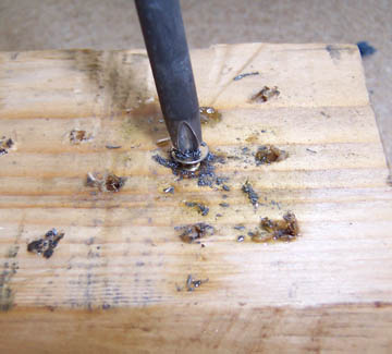
The brake cylinder (seperate "master" cylinder for each of the 4 brake peddles) fittings are 1/4 pipe thread on one end and crush fittings on the other -- all brass.
They install on the brake cylinders pointing up. I could have (maybe should have) installed these while the cylinders, or at least the rudder peddle assymbly, was on the bench.
I canted the bottom fittings inward toward the opposite cylinder in order to avoid routing the lines near the peddle where the pilot's foot will be during flight.
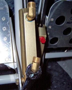
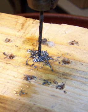
The first set of lines carries the brake fluid down from the brake fluid reservior. The lines are roughly measured and cut to length.
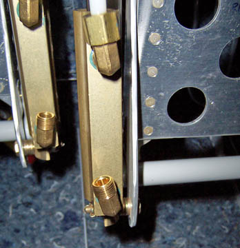
A full set of lines are installed on the right side of the cockpit. The top set come from the brake reservior and the bottom set feed the left side cylinders.
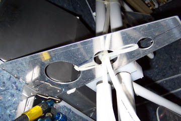
Where the brake lines cross along the top of the rudder peddle center support and through the hole in the support, a couple of pull ties suspends the lines so they don't make contact with metal edge.
|
|||||||||
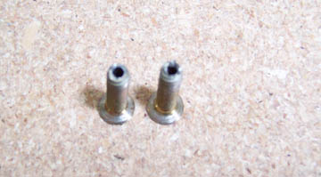
After giving it more thought, I decided to add a second static system. Why? Yeah, sounds unnecessary, doesn't it? Well, this airplane has separate electrical systems, separate pitot systems and other redundant systems. The redundant pitot systems both fail if the static system fails. I could either opt for the alternate static system internal to the cockpit or a completly redundant system. There is but a coupld ounces weight penalty for the truly redundant system. It starts by drilling holes in 2 #6 screws.
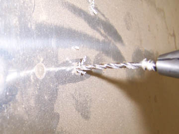
Alignment is critical. A #8 screw would make it easier, but it isn't necessary. Starting with a straight hole in a block of wood and positioning it on the drill press is key.
When the hole is drilled the screw can be backed out of the wood with a screwdriver.
Oops! A blurry picture, but hopefully, you can see the holes through the #6 screws.
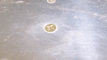
Next we drill out a rivet in the side panel, per plans.
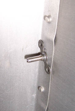
The screw is in place.
On the inside, the screw is held in place by a nutplate. It doesn't have to be riveted in place, since it can't turn or loosen on its own. This idea courteousy of Dennis Mangan.
Previous Day | HOME | Next Day |
|||||||||
| ... | |||||||||