| February 13, 2008 | HOME | ||||||||
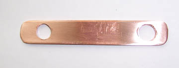
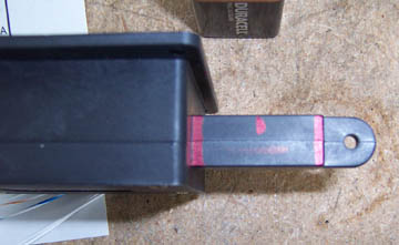
I made 4 of these copper straps to connect the master relay to the starter relay per plans. Yes, I made 4, because I have 2 independent electrical systems I need 2 sets of 2. I will install them later.
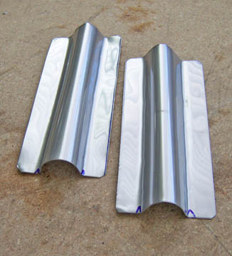
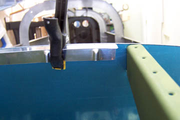
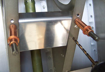
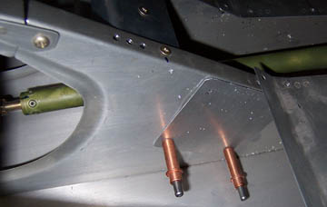
After much looking at through-firewall fittings and methods, I decided to take my own approach. I am starting with these stainless steel shields that I fabricated from some .035" stainless sheetmetal. I simply bent them around a piece of 1/2" pipe.
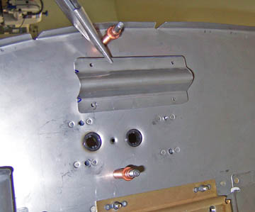
I matched drilled holes to the firewall and added nutplates. I then drilled holes for the wires to pass through and inserted grommets.
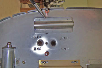
This might be a better view. When the wiring is finalized, I will fill the half-tube with fireblock calk. There should be no pathway for flame.
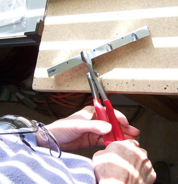
I turned my attention back to the panel installation and clamped these support brackets (you have to make them) to the panel to get the right curvature.
Some trial and error fluting gets it right.
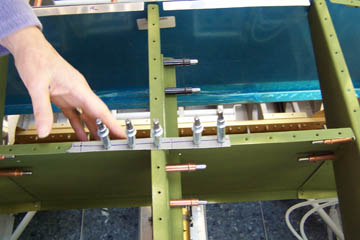
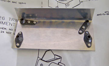
I also made a temporary template to make sure I had the rivet holes aligned. It isn't really necessary, but I wanted to get things squared up before I made the last of the attachment fittings.
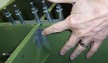
This small angle brace is an example of why I felt I needed to get the proper alignment. If it were off (if the holes weren't aligned) the brace would keep the top skin from aligning with the rivet holes. That would be another challenge.
|
|||||||||
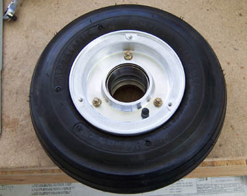
I took a break and assembled the nose gear tire, tube and wheel. I still need to pack the bearings before I can install it.
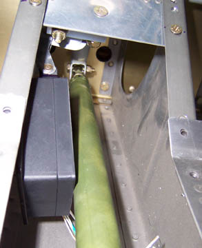
I bent a piece of .060" to hold the electric aileron trim actuator arm.
Nutplates (per plan) are installed on the underside so it will be screwed down with the floor pan.
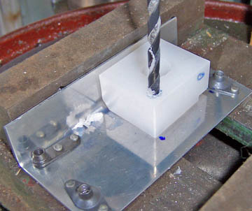
Match drilling the nylon block is a drill press job, but simple.
he next step is the set the trim servo to it's middle or neutral position. I ran it out full length using a 9 volt battery so I could mark the center.
Since I couldn't reach the mounting point very well, I made an aluminum template, first match drilling the template to the trim servo and then match drilling the mounting location to the template. That worked well.
When the servo is attached to the actuator bellcrank, it is a tight fit getting it all installed but it fits.
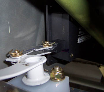
Here is a view of the servo (in back) attached to the bellcrank. It may help to know that this view is from underneath so the bellcrank appears upside down.
Previous Day | HOME | Next Day |
|||||||||
| ... | |||||||||