| September 20, 2008 | HOME | |||||||||
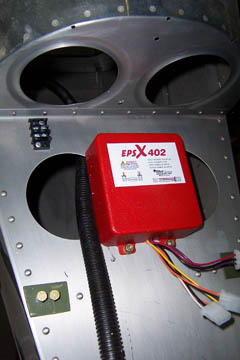
This strobe power pack has been hanging around waiting to be installed in the tail under the horizontal stabilizer. After moving it around the work area at least a dozen times over the last 6 months, I finally did something useful with it. A few minutes work and it is where it belongs.
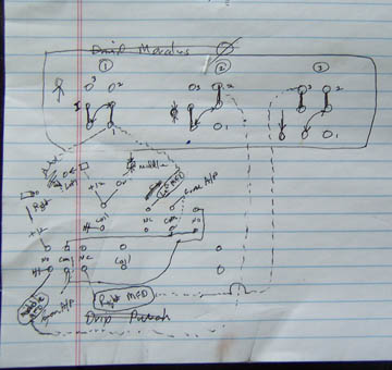
It being time to wire the switch relay box, I worked on this simple diagram of how it should work. Looks real professional, right. (O.K., no emails!)
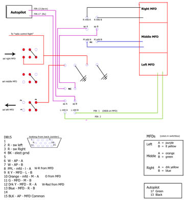
Here, it translates to something I find easier to understand, even if you don't. Believe me, this diagramming of wiring business is something I know nothing about. It is seemingly a matter of drawing pictures to represent what one needs to do.
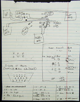
Another diagram to lay out the wiring including color coding and DB connector pinouts. All this will get drawn on the computer a little later.
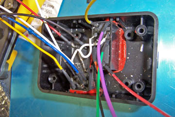
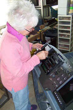
Wiring the relays in the relay switch box went as planned and took a lot less time than I expected.
|
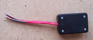
The relay switch box is closed up and sealed. All that needs to be done is to add the DB connector and install the box behind the panel.
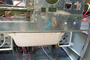
Imade an aluminum and fiberglass perch for the throttle quadrant. I have abandoned my original plan to use a lever system, but I want the whole thing to look built into the panel and not like a little aluminum add-on.
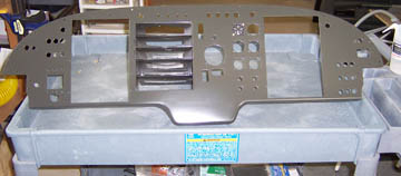
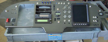
Here is the finished product on the painted panel. I used a flattening agent in the paint to keep the panel from being too reflective. It worked pretty well.
Once the paint dried, there was no need to rush to get the instruments into the panel, so I waited about 30 minutes!
That second MFD just can't sit on the bench by itself. One more piece of the panel installed! Now it will probably all have to come out again at least once...
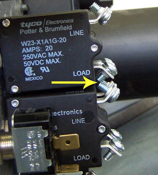
Oh yes, no surprise, there always has to be something that doesn't fit as planned. Those screws on the terminal posts aren't too close, are they?
Previous Day | HOME | Next Day |
|||||||||
| ... | ||||||||||